A facade that radiates heat upward to the cold sky while shielding pedestrians from its warmth. Achievable today with FDM-printable sawtooth geometry plus a two-coating finish — not a meta-surface, just clever angles. Estimated UTCI improvement: −6 °C on a summer heatwave noon, taking pedestrians from "strong heat stress" into "moderate heat stress" without lowering air temperature.
01 The Trigger
A Japanese maker on X showed a 3D-printed panel whose colour shifts dramatically with viewing angle. The mechanism is structural colour from the periodic surface micro-grating left by FDM print layers — interfering visible-spectrum light at angle-dependent wavelengths. The post asked nothing thermal. But the principle — different optical behaviour per direction — is exactly what passive cooling design has been chasing.
Question: can we do the equivalent at thermal infrared wavelengths (8–13 μm), so a building radiates strongly to the sky and weakly to people?
Honest disclaimer: the photo is an analogy, not a working IR cooler. Visible structural colour requires features at sub-μm scale (FDM print lines do this naturally at ~100–300 μm pitch, in higher diffraction orders). IR thermal radiation lives at 8–13 μm — print lines are too coarse to act as a sub-wavelength meta-surface there. So we don't get free angular IR behaviour from a normal print finish. What we do get, easily, is angular behaviour from macro-geometry — sawtooth ridges at mm-scale, with two different coatings on the two facets.
02 The Principle — A Thermal Venetian Blind
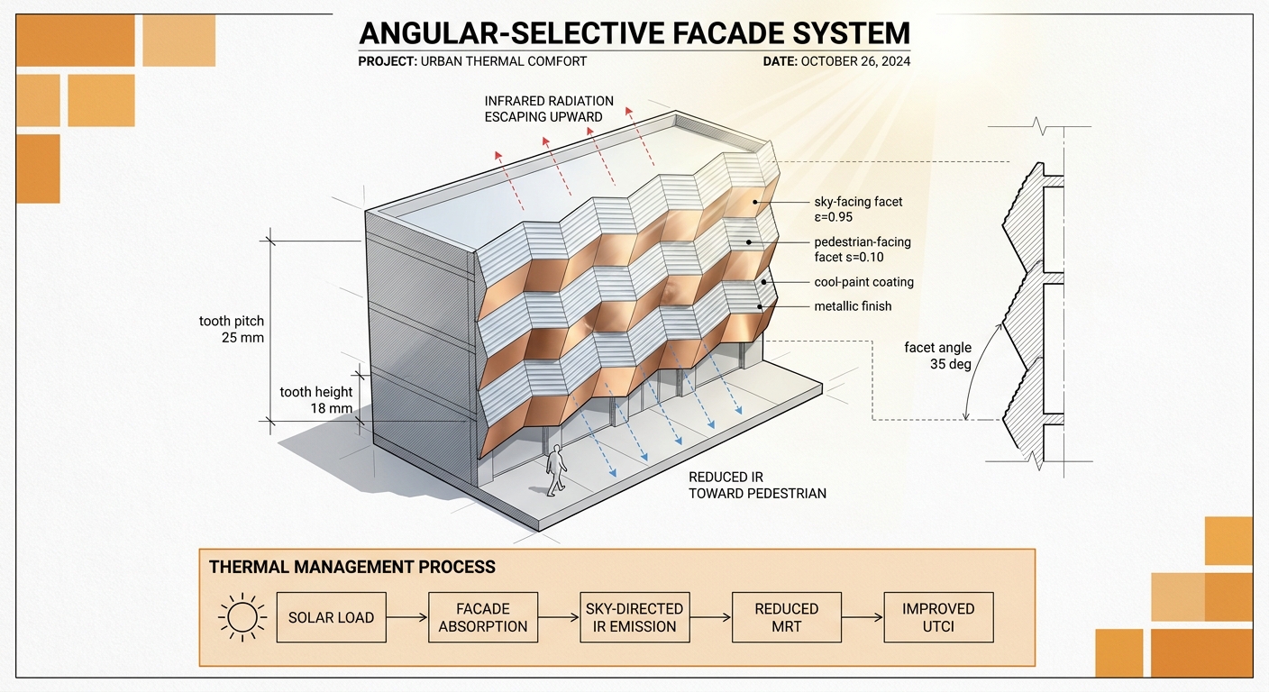
Fig 1 — Concept. Sawtooth ridges run horizontally on a facade panel. The upward-facing facet is coated with a high-emissivity cool-paint (ε ≈ 0.95 in the 8–13 μm atmospheric window). The downward-facing facet has a polished low-emissivity metallic finish (ε ≈ 0.10). Net effect: the facade dumps heat to the cold sky, but radiates very little toward the pedestrian below.
Two physical levers, in series:
Sky as a heat sink. Under a clear daytime sky, the effective sky temperature in the 8–13 μm atmospheric window is ~−15 to −20 °C even when ambient air is +30 °C. A high-ε surface aimed at the sky radiates ~80–100 W/m² of net cooling (Raman et al., Nature 2014).
Direction-selective emission. Emissivity is a property of the surface, not of the volume. By rotating the high-ε face up and the low-ε face down, the same panel becomes a strong radiator to the sky and a weak radiator to people.
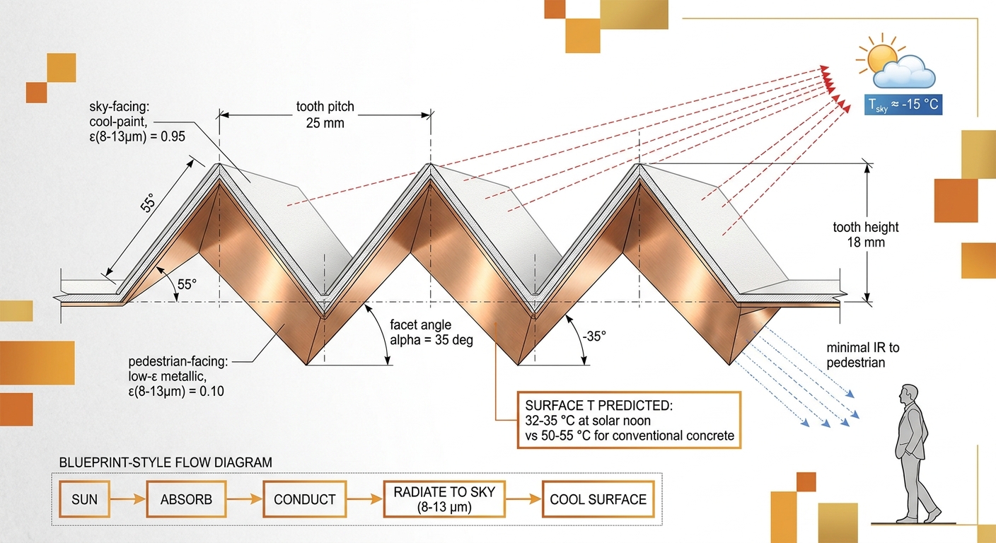
Fig 2 — Geometry detail. Pitch 25 mm, tooth height 18 mm, facet angle 35° from vertical. The sky-facing facet is matte cool-paint (LBNL-class spectrally-selective coating); the pedestrian-facing facet is anodized aluminium or copper. Predicted surface T at solar noon: 32–35 °C, vs 50–55 °C for conventional concrete.
03 Energy Balance
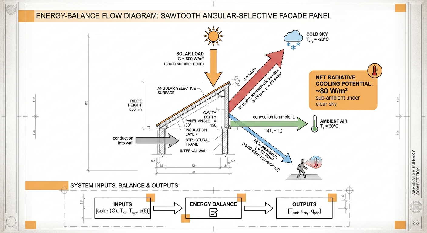
Fig 3 — Energy fluxes at solar noon, south-facing, clear sky. Solar input ~600 W/m² is partly reflected, partly absorbed. The absorbed fraction is shed via four paths: long-wave IR to the sky (large, ~90 W/m²), long-wave IR to pedestrians (small, ~12 W/m² — ~85% reduction vs conventional), convection to ambient air, and conduction into the wall. Net radiative cooling potential under clear sky: ~80 W/m² sub-ambient.
The 80 W/m² figure is what makes daytime sub-ambient cooling possible. Stanford's 2014 demonstration achieved ~5 °C below ambient at noon under direct sun with a multilayer photonic stack. We don't need that level of selectivity — we need the directional story, which is much easier to manufacture (paint two faces of a print).
04 Geometry Options
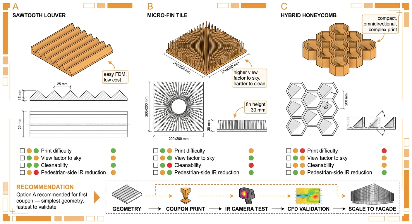
Fig 4 — Three printable variants. A: sawtooth louver (simplest, fastest to validate). B: micro-fin tile (higher view factor to sky from any azimuth, but harder to clean and more print-time). C: hybrid honeycomb with internal angled reflectors (compact, omnidirectional, but complex print and lower yield).
For first-coupon validation, Option A (sawtooth louver) wins on every axis except cleanability. It's printable on a Prusa MK3S in PLA-PET, requires only two paint passes (one masked), and its 1D geometry makes the CFD validation step ~10× cheaper than B or C.
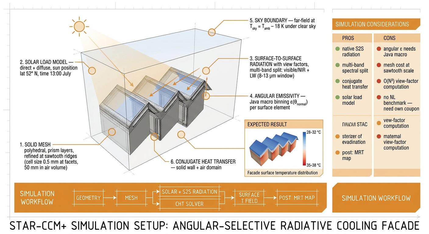
05 Can We Simulate It in STAR-CCM+ 21.02?
Fig 5 — Proposed STAR-CCM+ setup. Polyhedral mesh refined to 0.5 mm at sawtooth ridges, 50 mm in the air volume. Solar load model with sun position (lat 52° N, July 13:00). Surface-to-surface radiation with view factors, multi-band split (visible/NIR + LW 8–13 μm). Conjugate heat transfer between solid wall and air domain. Far-field sky boundary at T_sky = T_ambient − 18 K.
Pros and cons of using STAR-CCM+ for this
Pros
Native surface-to-surface (S2S) radiation with view-factor solver.
Multi-band spectral split — separate visible/NIR for solar absorption from LW for emission.
Conjugate heat transfer (solid + air domain) is standard.
Solar load model with date/time/lat sun position.
Sky radiation boundary via effective sky temperature is well-supported.
Mesh refinement at the sawtooth ridges is feasible without exotic settings.
Output couples directly into the Thor MRT/UTCI post-pipeline.
Cons
Angular emissivity ε(θ) is not exposed in the GUI — needs a Java macro to bin emissivity per surface element by the angle between surface normal and outgoing ray direction.
Mesh cost: full-facade resolution at mm-scale ridges is expensive. Use a representative section + periodic BCs for validation, then a coarser homogenized BC for the full facade.
O(N²) view-factor computation hurts large facades. Workaround: compute VF on the representative section, reuse.
No NL-context measurement data for an angular-selective coating yet — we have to build our own coupon validation. STAR-CCM+ alone proves consistency, not correctness.
Wind-induced convective coupling on louvered surfaces is a separate CFD problem (separation, wake mixing). For first cut, treat h_conv as a calibrated constant from coupon test.
Long-term soiling and tarnish are not in the model — they degrade ε over months. Real-world performance will drift.
06 Estimated Comfort Improvement
These are predictive estimates, not measurements. They are derived from a simple two-node radiative balance using literature ε values, KNMI reference T_air for De Bilt, and clear-sky T_sky from the Berdahl–Martin atmospheric window correlation. They are not validated against a built facade — that's exactly what the coupon-test step in §07 is for. Expect ±2 °C error bars on T_mrt and ±1.5 °C on UTCI until coupon data lands.
Assumptions used (the same for both seasons)
South-facing facade, urban canyon (W/H ≈ 1), pedestrian standing 2 m from wall.
Solar noon, clear sky, light wind 1.5 m/s.
Pedestrian: light summer clothing, 1.2 met activity, 1.75 m height, 75 kg.
Conventional reference: bare concrete, αsolar = 0.55, εLW = 0.92.
T_sky derived from T_air using Berdahl–Martin under clear sky (window-band T_sky ≈ T_air − 18 K).
Spring (mid-May, clear noon, T_air = 18 °C, G_solar = 700 W/m²)
Metric
Conventional concrete
Treated sawtooth
Δ
T_air at pedestrian
18.0 °C
18.0 °C
0
Wall surface T
38 °C
24 °C
−14
T_mrt at 2 m from wall
32 °C
22 °C
−10
UTCI
21 °C (no thermal stress)
19 °C (no thermal stress)
−2
In spring, both cases are within UTCI's "no thermal stress" band. The MRT delta is large but doesn't change comfort category. The benefit shows up as shoulder-season comfort margin, not as an immediate user-felt improvement.
This is the case that justifies the work. UTCI moves a full category — from "strong" to "moderate" thermal stress — without a single watt of active cooling and without lowering air temperature. The lever is entirely radiant: the wall stops being a 50+ °C radiator pointed at the sidewalk.
The trick is in what doesn't change. T_air barely moves (urban-canyon mixing dominates), so an air-temperature-only metric would miss this. T_mrt is where the win lives — and UTCI weights T_mrt almost equally with T_air, which is why the comfort category shifts.
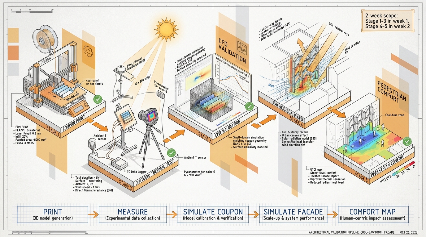
07 Validation Pipeline — How We'd Build the Evidence
Fig 6 — Validation pipeline. Print → measure → simulate-coupon → simulate-facade → comfort map. The CFD step is gated by coupon-test agreement; the facade step is gated by CFD-coupon agreement. Each gate fails openly — we don't paper over disagreement.
2-Week Scope
Day 1–2 (Print + coat). Print 100×100 mm sawtooth coupon on Prusa MK3S in PLA-PET. Mask and spray sky-facing facets with LBNL-class cool-paint. Polish or anodize ped-facing facets.
Day 3–4 (Outdoor thermal test). Mount on south-facing stand at lab. FLIR + 4× thermocouples on facets, 1× ambient probe, pyranometer for G. Log 48 h of clear-sky data.
Day 5–7 (CFD coupon). STAR-CCM+ small-domain match: same geometry, same solar load, sky T from Berdahl–Martin on test day. Acceptance: predicted facet T within 2 °C of measured at noon.
Day 8–10 (CFD facade). Scale to 3-storey south-facing facade in a Haarlem street section already meshed for the ABT demo. Replace facade BC with the angular-selective wall macro.
Day 11–12 (UTCI map). Plug surface T field into the existing MRT/UTCI post-pipeline. Render a sidewalk comfort map with/without the treatment. Same plot template as the Veilingstraat compare-tool.
Day 13–14 (Diary + ABT integration). Write up the coupon→CFD agreement (or disagreement). If agreement holds, slot into the ABT demo as "Intervention #4: angular-selective facade" alongside white walls / trees / combined.
08 Honest Limits
Soiling kills the cool-paint. Spectrally-selective coatings rely on micron-scale surface optics; dust and soot raise solar absorptance by 0.05–0.15 within a year. Maintenance schedule needs to be in the spec.
Tarnish on the metallic facet. Bare aluminium oxidizes to AlOₓ which raises ε from 0.05 toward 0.2. Anodized hardcoat or PVD finish is the realistic spec; bare polish is a coupon-only convenience.
Rain and snow loading. Sawtooth ridges trap water in the bottom of each V. Need a small drip channel along the ridge or a slight tilt off-horizontal.
Wind-driven convection alters the energy balance. Strong wind raises h_conv and shorts the radiative win. Effect is largest on exposed corners, smallest in protected canyons. Couple with our existing wind LBM solver, don't pretend it's still — radiation.
Cloud cover collapses the sky sink. Overcast T_sky can be only 5–10 K below T_air. Net cooling potential drops by ~70%. The comfort case is a clear-sky case; cloudy conditions are not where the value is.
Bird strike on horizontal ridges. Not yet considered; need a visual disruption pattern at facade scale, similar to UV-fritted glass.
No NL-context measurement reference. Most published radiative-cooling field tests are in California, Arizona, or Saudi Arabia — much drier skies. NL coastal humidity narrows the atmospheric window. Coupon test is the gating evidence; we cannot import a Stanford number.
09 Where This Slots in the Lab
Lijn 2 (Radiation): directly extends pvlib + trimesh self-shadowing to include directional emissivity. The MRT post step already exists in the Haarlem demo.
Lijn 4 (STAR-CCM+): adds a Java macro for angular ε(θ) — banks a reusable scaffold for any future spectrally-selective surface (cool roofs, sub-ambient panels, transpired solar collectors).
Lijn 6 (Agent dialogue): "What if we treated this south facade as a sky radiator?" becomes a question the agent can answer with a concrete UTCI map, not a vague yes-but.
ABT demo (26 May): a 4th intervention category alongside white walls, trees, combined — the only intervention that doesn't require new street-level infrastructure or watering.